Installation of controllers (photo gallery)
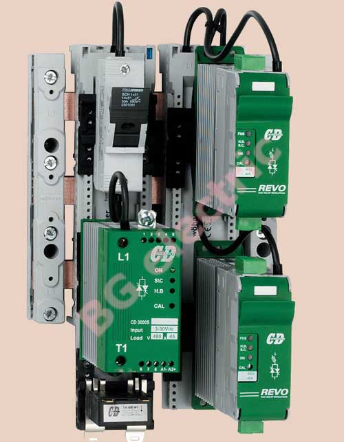 |
1. In this picture you can compare how much more space is saved in the cabinet when using the new REVO family of regulators compared to the old CD3000 family. On the left is a single 45A CD3000S regulator, with a current transformer below it and an external fuse holder above it. Two 45A REVO-S regulators are mounted in the same space on the right, each including a current transformer and fuse. Actual economy of space. Actual space saving of 50% in the enclosure allows for smaller enclosures and significant savings in installation time and materials. |
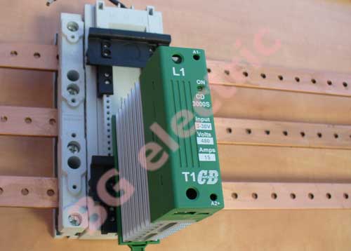 |
2. The thyristor regulators are mounted on an insulating support placed directly on the three-phase copper power busbar. The support is secured to the busbar with a latch and performs several functions, including providing electrical contact with the supply line. Alternatively, the support can be bolted to the rear wall of the enclosure, in which case it is itself a support structure for the power bus. On the front surface of the support there is a two-level DIN-rail holder, on one of which a thyristor regulator is mounted. |
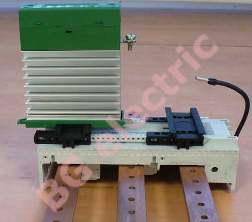 |
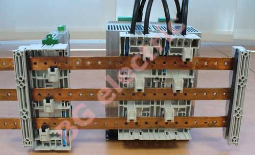
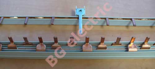
3. This picture clearly shows that the distance between the two rows of DIN rails can be adjusted for ease of installation and proper layout. The structure has screw terminals at the top that automatically make contact with the power supply busbar from which the power supply cables are routed. |
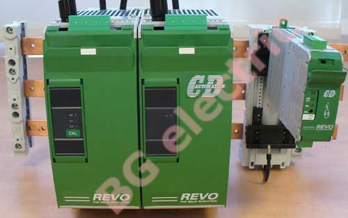 |
4. Mounting thyristor regulators of different sizes using insulating supports of different designs and widths. |
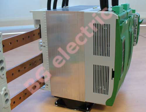 |
5. Installation of thyristor regulators on a three-phase busbar, side view. |
 |
6. Isolating universal support, rear view, regulator removed from supply rail. |
 |
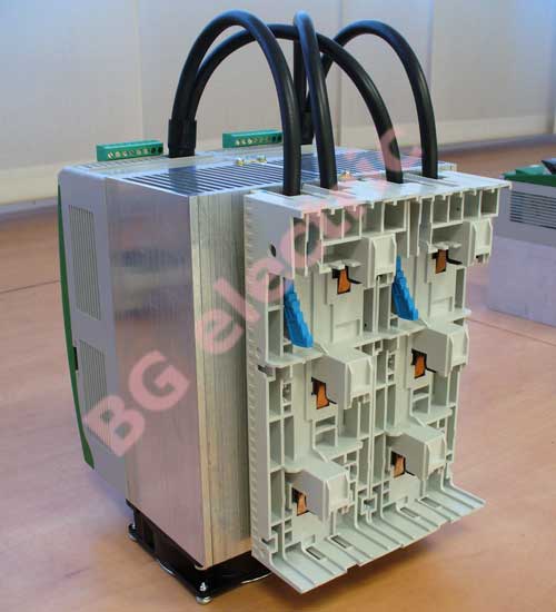
7. Assembly of thyristor regulators, complete structure, rear view. |
 |
8. Installation of thyristor regulators, the use of special insulating support allows minimizing time and costs for installation of regulators. |
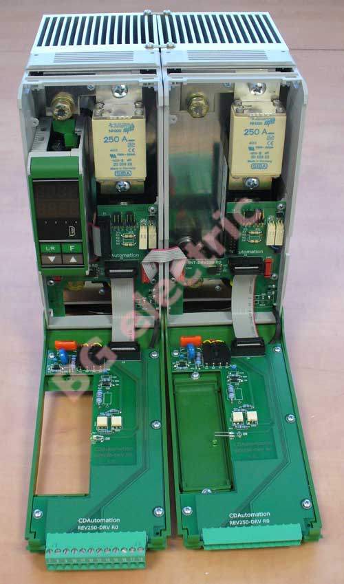 |
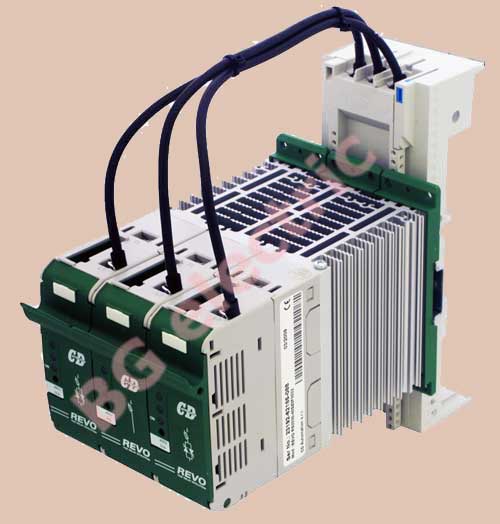
9. REVO TC thyristor regulator for 210A, consisting of two modules for power regulation in a three-phase load without neutral on two channels. On the left you can see the integrated PID controller, above are the fast fuses. |
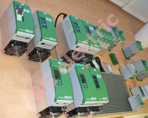 |
10. REVO thyristor regulators of larger size in various versions with load current 60...210A. The regulators have various mounting options, always taking into account the mandatory convection of the cooling air through the heat sinks. |
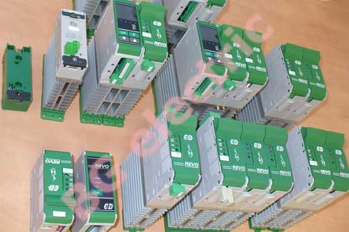 |
11. The smaller REVO thyristor regulators in various versions with a load current of 30...45A can be mounted either on a DIN rail or on a flat surface. |
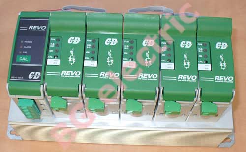 |
12. The smaller REVO-S thyristor regulators can be connected to each other using a flat cable, for this purpose special connectors are provided in the upper part of the regulator. The flat cable supplies power to all modules and signals the status of the load and power thyristors, i.e. the use of a flat cable is especially justified when the "Heater break alarm" function is activated. Регуляторы могут быть смонтированы на едином радиаторе как с воздушным, так и с водяным охлаждением. Эта технология позволяет снизить затраты на монтаж при большом количестве регуляторов, например, при управлении многозонным нагревом. For every 14 REVO-S modules, one REVO-TU module must be installed to combine control, calibration and notification functions. |
 |
13. For convenience and cost savings when mounting thyristor regulators, single- and three-phase busbars (strips) are available, mounted on several side-by-side modules to supply power to the power thyristors and load. Each such busbar has one terminal for connection to the supply network. |
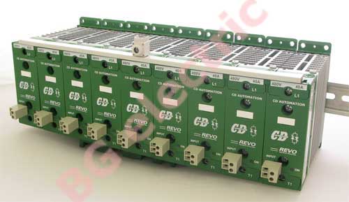 |
14. The single-phase load supply busbar is mounted on a row of regulators (top, front, in white insulation), with the common power supply terminal on top. |
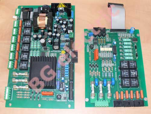 |
15. Spare parts, including control boards, are available for all types of regulators supplied. |
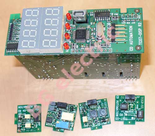 |
16. Spare parts are available for all types of regulators supplied, including embedded PID controller boards. |
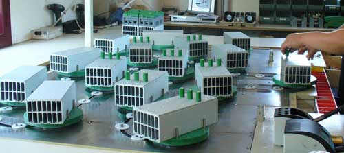 |
17. Flow line for processing of heat sinks of thyristor regulators of REVO series. Photo taken at the assembly area of the plant in Legnano (Italy). |
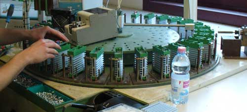 |
18. Assembly carousel of CD3000S and CD3000M series single-phase thyristor regulators. Photo taken at the assembly area of the plant in Legnano (Italy). |
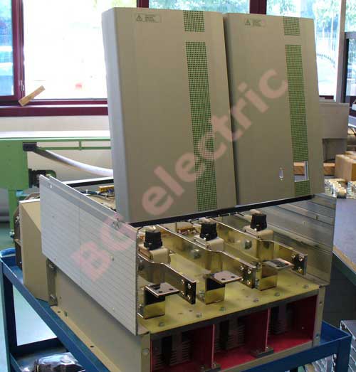 |
19. Assembly of a three-phase MULTIDRIVE thyristor regulator with a current of 1600A for a Russian customer. The cable power inputs are located in the upper part of the housing. After final assembly, the regulators undergo full-scale testing under load in various operating modes. The photo was taken at the assembly area of the plant in Legnano (Italy). |
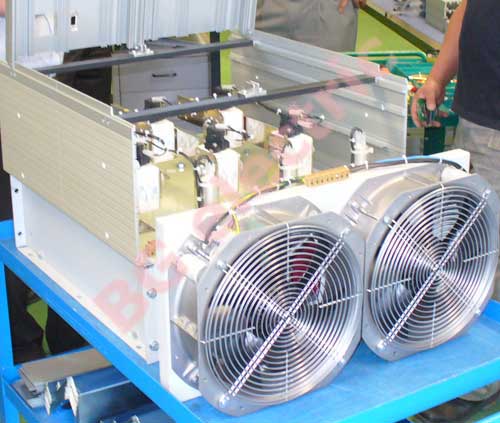 |
20. Assembly of a three-phase 1600A MULTIDRIVE thyristor regulator for a Russian customer. Two powerful fans are located at the bottom of the housing to ensure effective cooling under the most unfavorable operating conditions. The weight of such a regulator is more than 90 kg. |
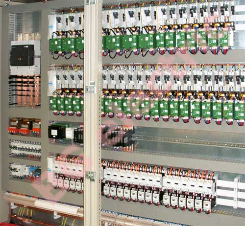 |
21. Installation of thyristor regulators in the switch cabinet. |